|
Flyin Optronics Co.,Ltd.
|
Thermal or Athermal AWG DWDM
| Payment Terms: | T/T,WU |
| Place of Origin: | Guangdong, China (Mainland) |
|
|
|
| Add to My Favorites | |
| HiSupplier Escrow |
Product Detail
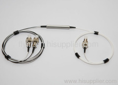
Flyin's Mini size Coarse Wavelength Division Multiplexers(Mini CWDM, MCWDM), are integrated optical modules using Flyin's proprietary optical bench
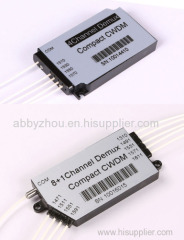
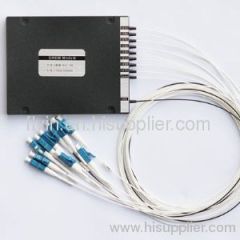
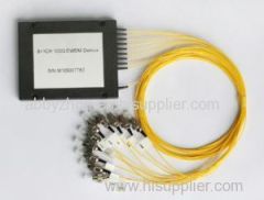
40 CH 100G AWG Module(40 CH 100G DWDM Mux/Demux)
Model : 100AWG
Flyin Optronics offers a full range of AWG products, including 50GHz, 100GHz and 200GHz AWG. Here we present the generic specification for the 40-channel 100GHz AWG MUX/DEMUX component supplied for use inDWDM system.
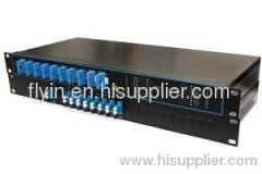
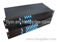
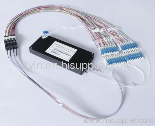
This component is designed for use within the C -band release of DWDM system. To decrease the power dissipation of the devices in different environmental conditions, the AWG package is special designed with selection of reliable thermal plastic with low thermal conduction, and the AWG operating temperature is controlled by using foil resist heater or Peltier TEC with thermistor temperature sensor. Different input and output fibers, such as SM fibers, MM fibers and PM fiber can be selected to meet different applications. We can also offer different package for different products, inluding special metal box and 19" 1U rackmount.
Optical Specification(Flattop AWG)
Parameters | Condition | Specs | Units | ||
Min | Typ | Max | |||
Number of Channels | 40 | ||||
Number Channel Spacing | 100GHz | 100 | GHz | ||
Cha. Center Wavelength | ITU frequency. | C -band | nm | ||
Clear Channel Passband | ±0.1 | nm | |||
Wavelength Stability | Maximum range of the wavelength errorof all channels and temperatures in average polarization. | ±0.05 | nm | ||
-1 dB Channel Bandwidth | Clear channel bandwidth defined by passband shape. For each channel | 0.4 | nm | ||
-3 dB Channel Bandwidth | Clear channel bandwidth defined by passband shape. For each channel | 0.6 | nm | ||
Optical Insertion Loss at ITU grid | Defined as the minimum transmission at ITU wavelength for all channels. For each channel, at all temperatures and polarizations. | 4.5 | 6.0 | dB | |
Adjacent Channel Isolation | Insertion loss difference from the mean transmission at the ITU grid wavelength to the highest power, all polarizations, within the ITU band of the adjacent channels. | 25 | dB | ||
Non-Adjacent, Channel Isolation | Insertion loss difference from the mean transmission at the ITU grid wavelength to the highest power, all polarizations, within the ITU band of the nonadjacent channels. | 30 | dB | ||
Total Channel Isolation | Total cumulative insertion loss difference from the mean transmission at the ITU grid wavelength to the highest power, all polarizations, within the ITU band of all other channels, including adjacent channels. | 22 | dB | ||
Insertion Loss Uniformity | Maximum range of the insertion loss variation within ITU across all channels, polarizations and temperatures. | 1.0 | 1.5 | dB | |
Directivity(Mux Only) | Ratio of reflected power out of any channel(other than channel n)to power in from the input channel n | 40 | dB | ||
Insertion Loss Ripple | Any maxima and any minima of optical loss across ITU band, excluding boundary points, for each channel at each port | 0.5 | dB | ||
Optical Return loss | Input & output ports | 40 | dB | ||
PDL/Polarization Dependent Loss in Clear Channel Band | Worst-case value measured in ITU band | 0.3 | 0.5 | dB | |
Polarization Mode Dispersion | 0.5 | ps | |||
Maximum Optical Power | 23 | dBm | |||
MUX/DEMUX input/ output Monitoring range | -35 | +23 | dBm | ||
IL Represents the worst case over a +/-0.1nm window around the ITU wavelength
PDL was measured on average polarization over a +/- 0.1nm window around the ITU wavelength.
Ordering Part Code Sequence
AWG | X | XX | X | XXX | X | X | X | XX |
Band | Number of Channels | Spacing | 1st Channel | Filter Shape | Package | Fiber Length | In/Out Connector | |
C=C-Band L=L-Band D=C+L-Band X=Customize | 16=16-CH 32=32-CH 40=40-CH 48=48-CH XX=Special | 1=100G 2=200G 5=50G X=Special | C60=C60 H59=H59 C59=C59 H58=H58 XXX=special | G=Gaussian B=Broad Gaussiar F=Flat Top | M=Module R=Rack X=Special | 1=0.5m 2=1m 3=1.5m 4=2m 5=2.5m 6=3m S=Specify | 0=None 1=FC/APC 2=FC/PC 3=SC/APC 4=SC/PC 5=LC/APC 6=LC/PC 7=ST/UPC S=Specify |
Didn't find what you're looking for?
Post Buying Lead or contact
HiSupplier Customer Service Center
for help!
Related Search
Thermal Insulation
Thermal Transfer
Thermal Printer
Thermal Protector
Thermal Paper
Thermal Relay
More>>
Find more related products in following catalogs on Hisupplier.com
Company Info
Flyin Optronics Co.,Ltd. [China (Mainland)]
Business Type:Manufacturer
City: Shenzhen
Province/State: Guangdong
Country/Region: China (Mainland)
|
Abby Zhou:
|